Use the SPI Signal type to see the Master/Slave data from two Synchronous Serial data channels using the SPI protocol.
Signal Name
Change the text displayed here to help you identify this signal definition. If the name has already been used, it will automatically be appended with a numerical value in brackets (i.e. [2]). The name displayed here will be used in the Waveform Views, Searches, Tabular Views, Exports, Trigger Configurations and all menu references.
Disable Signal
Check this item to completely disable the Signal Definition. It is recommended to disable any signals that use channels that are not connected to a physical device. When a capture takes place ("Run"), any channels that are assigned to disabled signals will be ignored instead of using valuable capture space.
Plot Output
Check this item to enable Plotting for this signal. If checked, all waveform views will display plotted data as defined by the Plot Series configurations. You must enable and configure at least one Plot Series before any plotted data is visible. Up to 4 individual plots can be configured for each signal. (see: Plotting Signal Data).
Color Selection & Examples
An example of the signal is displayed in the current color scheme, followed by an example of the current color selections for this signal and a color reset button. Clicking on one of the color squares will open the Color Selection dialog to change the Signal line color and its background color if a color other than the theme color is desired.
Reset Signal Colors
This button will reset the colors for this signal so that they will match the currently selected color theme (see: Color Themes).
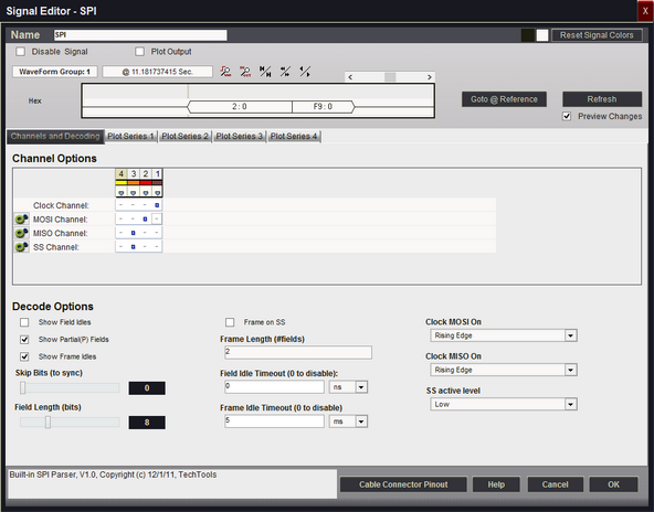
Channel Options
This is where you will associate a signal definition with the physical channels or connections to the outside world. Each signal definition type will have one or more channel selection groups and will allow one or more channels to be selected for each group. Each channel selection group will be identified on its left if more than one group is available for the signal type.
To select a channel, click on the " - " below the proper color (and channel number) that corresponds to the physical connection of the DigiView Cable (see: Connecting the Data Lines). Channels that are selected for this signal will replace the " - " with a blue square as shown above. The gray arrow beneath each channel color is an activity indicator that displays the activity of the channel as compared to the activity of all the other channels (relational, not real time).
Clock Channel Selection
Selects which physical channel to assign to the CLOCK.
MOSI Channel Selection
Selects which physical channel to assign to the MOSI data.
Invert Channels
If selected, the captured data for MOSI will be inverted before decoding and displaying (only affects this Signal Definition).
MISO Channel Selection
Selects which physical channel to assign to the MISO data.
Invert Channels
If selected, the captured data for MISO will be inverted before decoding and displaying (only affects this Signal Definition).
SS Channel Selection
Selects which physical channel to assign to SS (slave select).
Disable / Ignore
If selected, the SS channel will be ignored when decoding this signal.
Invert Channels
If selected, the captured data for the SS channel will be inverted before decoding and displaying (only affects this Signal Definition).
Clock MOSI On
Specifies which clock edge to use to strobe in MOSI data.
Clock MISO On
Specifies which clock edge to use to strobe in MISO data.
SS active level
Specifies the active level for the SS (slave select) signal.
Field Idle Timeout (0 to disable)
A new field is started if no new bits are seen for more than the specified time. Set to 0 to disable.
Skip Bits (to sync)
Specifies how many bits to ignore at the start of the buffer. Useful for syncing up when capture starts mid-field
Field Length (bits)
Specifies the data field length from 4 to 24 bits.
Show Field Idles
Specifies whether idle time between fields should be shown as a hashed field or if the current field should just extend to the next field.
Show Partial(P) Fields
Specifies whether to show partial fields or not. Partial fields were terminated (by timeout or SS) before they gathered the full bit count.
Show Frame Idles
Specifies whether idle time between frames should be shown as a single center line or if the current frame should just extend to the start of the next frame.
Frame Length (#fields)
Specifies the number of fields to include in a frame (if fixed length).
Set to 0 to disable.
Frame Idle Timeout (0 to disable)
A new frame is started if no new bits are seen for more than the specified time. Set to 0 to disable. This can be useful if there are no sync lines or field counts but you can see a consistent pause before each frame starts.
Frame on SS
Specifies that we should terminate a frame on SS disable edges and start a new frame on SS active edges.
Plot Series 1 - 4
If "Plot Output" is selected, up to 4 plots can be defined. If enabled and at least one Plot Series is defined, all waveform views will display the data in a plotted format. (see: Plotting Signal Data).
Display Fields
MOSI-MISO
Field type used to show normal data.
Shows the both data channels, separated by a colon: ' MOSI : MISO '
(P)MOSI-MISO
Field type used to show partial (interrupted) data fields.
Shows '(P)' followed by both data channels, separated by a colon: ' (P)MOSI : MISO '.
NOTE: Multiple framing methods can be used at the same time. For example, you could use a frame length specifier and the frames will be broken into the specified lengths. If a timeout is specified, it will override and terminate a frame if the specified time is exceeded.