Current DigiView hardware has either 9, 18 or 36 physical channels. However, we like to think in terms of symbolic names representing individual signals (clock,ALE) or groups of signals (DataBus, Address) rather than channel numbers(0,1,2..). We start by defining SIGNALS in terms of CHANNELS. This is the only place we deal directly with physical channels. The remainder of the software deals in terms of signal names rather than channel numbers. When we define signals, we are mapping a signal NAME to one or more physical channels. This also makes it possible to share the same physical channel with multiple signal definitions (see: Signal Editors).
Adding Signals to the Project
To create a Signal, select the "Add Signal" button from Tool Bar (highlighted above, or use the "Create Signal" button in the Project Configuration Options window).
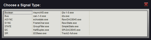
Click on one of the selections to create a new signal. A new signal of the chosen type will be created and it's property editor will appear. You can rename the signal, select the physical channels to capture and set all associated options from the signal's editor. (For details on signal options, see the section: Signal Editors) Use the Escape Key or the red close button if you do not wish to add a signal.
Summary of the Project's Signals
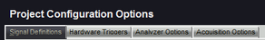
Signals added to the project are listed in the Project Configuration Options window on the Signal Definitions tab. To access the Project Configuration Options window, click the Project Settings button on the tool bar (highlighted above) then select the "Signal Definitions" tab.
The main purpose of the lower section of this tab is to provide an overview of all current signal definitions and their related channels. You can also Edit or Delete signals from this section, determine each signal's type, its basic colors and its enabled status.The Project Signals section is arranged in a grid with columns representing the physical channels and one row per defined signal. Notice that the same channel can be assigned to multiple signal definitions. In the image below, channel 8 has been assigned to several signal definitions (AD0-15, CODE, address, RD-DATA, WT-DATA).
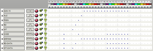
Channel 0 is in the farthest right column and the highest channel number is in the farthest left column (as marked in the header.) A line appears every 4th channel (or nibble) for clarification.
In addition to the color references at the top of the window, you can click on the 'Cable Connector Pinout' button at the bottom of the window to see a physical layout of the attached analyzer's channel connector with channel numbers, ground connection locations and the color code of each channel.
Note: It is important to enable only channels that are actually being connected to your circuit. The remaining, unconnected channels will be floating and will most likely pick up noise or power line hum. If enabled, these transitions will get stored, wasting storage space. It is also important to connect the black ground wires to your target's ground so that the analyzer and the target have a common ground reference. It is recommended to place the ground connections as close to the channel connections as possible.
Changing the Signal order - 
When adding a large number of signal definitions, you may want to change some of their positions to organize or group related signals. To change the display order, grab the small handle in the left margin with your mouse and drag the definition to a new position.
Signal Name - 
The name of this signal definition. This value can be changed by editing the signal's properties. (see: Signal Editors)
Signal Colors and Type -  ,
,  ,
,  , etc.
You can see the color of a signal and determine the type by this graphical indicator (displayed to the right of the name assigned to the signal). Each signal type will display a unique graphic with representative colors.
Delete Signal - 
You can delete a signal definition by clicking on the 'X'.
Edit Signal Properties - 
You can change the properties of a signal definition by clicking this button. (see: Signal Editors)
Enabled Status/Toggle - 

Indicates the enabled state of the signal. When the lightbulb is ON, the signal is enabled. Click this button to toggle the "enabled" status of the signal. This value can also be changed by editing the signal's properties. (see: Signal Editors)
Associated Channels - 
All channels associated with this signal definition will be indicated in this display as a square blue "dot". Channel 0 is in the farthest right column and the highest channel number is in the farthest left column (as marked in the header.) Light lines appear every 4th channel and non associated channels appear as a short dash. Also, colored squares at the top show each channel's wire color. Notice that there are only 9 colors so the color sequence repeats using resistor color code order (the color Black is used for ground connections - channels 0, 9, 18 and 27 are brown).