DigiView provides several Signal type definitions which allow unique methods of interpreting and displaying the raw data captured on the logic channels. Each Signal type has a unique editor with relevant options for its type. From the editor you will also assign some of the physical logic channels to be used for this new signal definition. (see: Connecting Data Lines)
You may choose to repeat the use of some channels in multiple Signal definitions in order to interpret the data differently and gain a perspective that is relative to your current point of interest. This can be done easily by creating a new Signal using the definition with the properties you require. Using the same channels in multiple definitions will not have any effect on the actual capture, but can greatly increase your ability to analyze the data and present visual representation to others.
NOTE: The same channel can be assigned to as many signal definitions as you need. For instance, if you want to capture the Read and Write cycles of an SPI bus using separate signal definitions (instead of the combined read/write of the SPI signal type), you can create 2 Synchronous Serial signals and assign the same channel as the Clock for each definition.
Signal Selection
The signal selection can be expanded by adding Plug-ins which can be downloaded with the software (as available) or created by using our free Plug-in Development Kit (downloadable from our website). The current 'built-in' Signal Types are listed below. Details of each type's properties are described in the following sections.
Serial UART analysis, pre-selected and custom baud rates, channel inversion option, from 4 to 8 bit selectable, parity option, Framing options and Glitch filter.
Single channel viewing.
Multi-channel viewing as a single value. Also suitable to display the capture of an Analog to Digital converter as an Analog Signal when the Plot Output option is selected (see: Plotting Signal Data)
Full featured Controller Area Network protocol decoder.
Complete I2C protocol analysis. 7bit/10bit addressing, High Speed Mode Master Codes, General Call support, Glitch filter.
Inter-IC Sound bus protocol decoder with word length selection from 4 to 32 bits.
Master/Slave data from two Synchronous Serial data channels using the SPI protocol.
Filters multi-channel data by state of a single channel, selectable CLK/DATA inversion, selectable transition state of Rising/Falling/Both, Framing and timeout options, additional Select and Sync channel for filtering.
From 1 to 32 bit protocols, also suitable for SPI analysis, selectable CLK/DATA inversion, selectable Rising/Falling/Both clock edges, LSB/MSB selection, additional Select, Frame Sync and Field Sync channels for filtering and synchronizing.
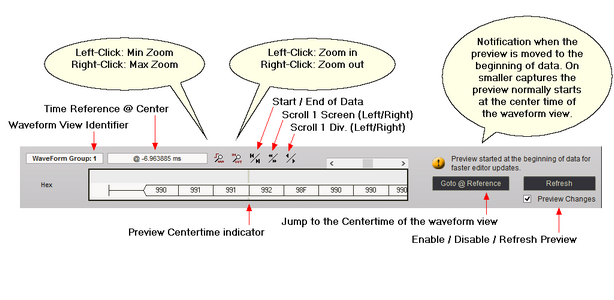
Signal Editor Preview
All signal editors provide a preview that updates while making changes to the signal's options. The time position and zoom level of the preview can be changed to get a better view of the data if needed. This area of the editor is explained below. The symmetrical function buttons below all use Left and Right mouse button clicks to perform opposite functions.