The level trigger is a pattern match detector. You can configure it to match any combination of 0,1 or "don't cares" across all channels. The Pattern Match Editor is displayed below
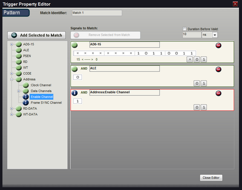
ADD a Signal - Highlight a defined signal from the left portion of the window and click the "+" button to add it to the Pattern Match. You can also just "Double-Click" the defined signal to automatically add it. NOTE: High Level signal definitions (such as State, I2C, or etc) cannot be added directly as a complete signal. However, the individual portions of the signal (such as Enable above) can be added in the same manner. To see the sub-portions of a signal, click the "expand" button in the left column next to the signal's name, then add the sub portions in the same manner as any other signal.
For instance, if you have defined a State signal like the one above (Address) and you only want to add the Enable signal to the pattern match, then expand it and double-click on Enable.
Note: If a signal is valid for the trigger configuration, a green icon will be displayed next to it. Any other icon, such as the blue circle above on the Enable and the Frame Sync channel of the Address signal, indicates a channel state that is invalid for triggering. The Blue icon in the Edit area for Enable indicates the channel has been configured as 'Ignored' in the signal definition editor and is generally "Disabled" (Blue icon in the selection tree on the left). The Red outline in the edit area indicates an invalid signal has already been added to the definition, making it invalid. When moving the mouse over an invalid signal match, a hint will display with additional details of the error.
Delete a Signal - Highlight a signal in the right portion of the window (or mouse-over its bit selections) and click the "-" button to delete it from the Pattern Match.
Changing Bit Pattern - Each bit of the signal can be toggled between the 3 states of '0', '1' and 'x' (don't care) by simply clicking on the bit position in the pattern edit area. To set all bits for a signal to one of these 3 values, use the X, 0 and 1 buttons to the upper-right of the pattern edit area.
Identifier - Change the identifier to something meaningful for the match condition if you do not want the default "Match #" to be displayed in the formula and the graphical configuration area of the trigger screen.
Duration - Enter the stability duration by selecting the units then typing the value. The Maximum Duration period for Models DV3200, DV3209, DV3400, DV3409 and DV3500 is 5 ms; 10ms for Models DV3100 and DV3109. The Trigger condition will not be considered as "True" until the selected signals (and bits) match the pattern for the indicated duration period.